
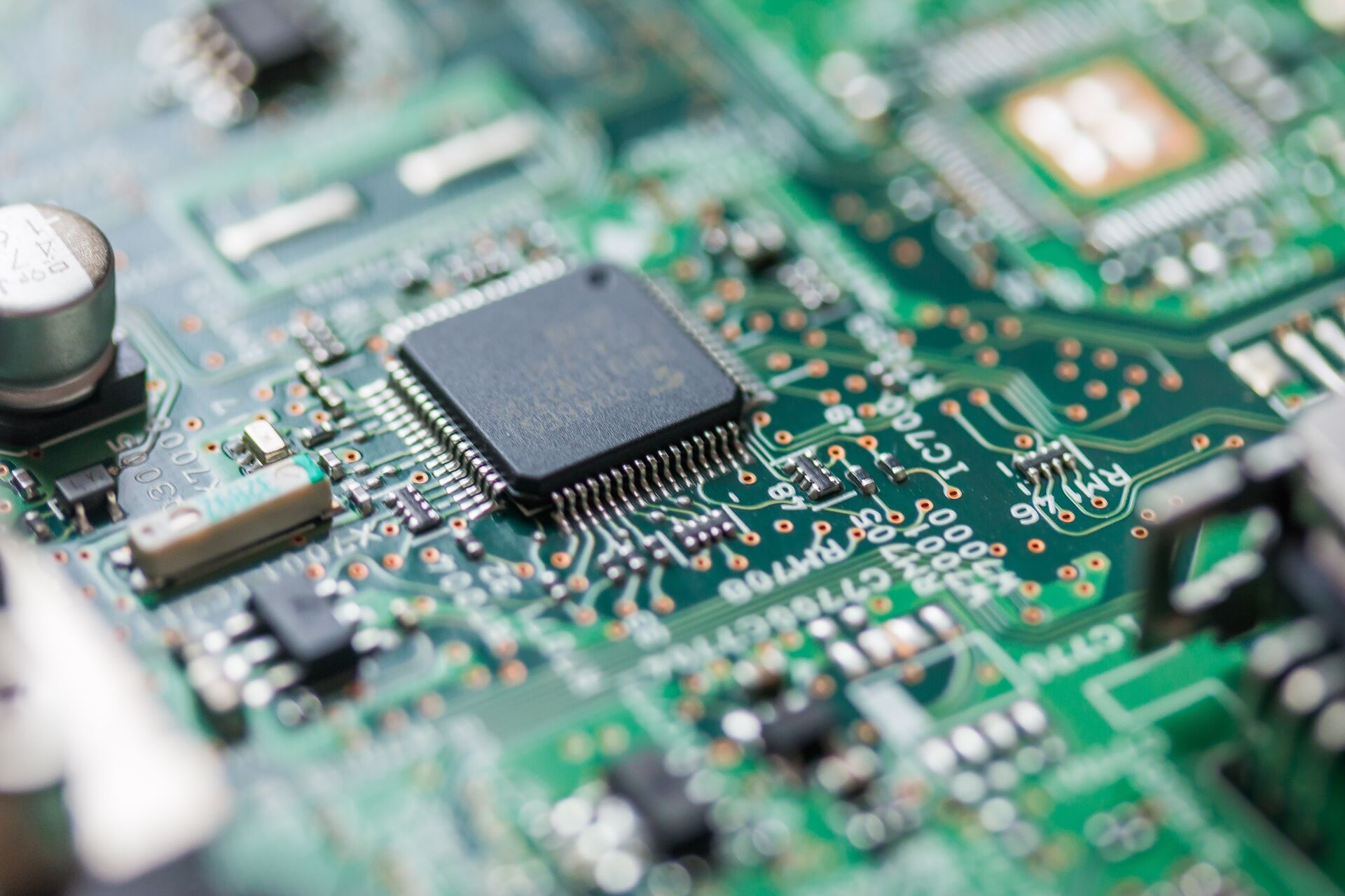
Failure Analysis and Quality Inspection in Electronics Manufacturing
Electronic assemblies are becoming increasingly complex and sensitive to process deviations. Even the smallest defects, soldering issues, or contaminants can lead to malfunctions, failures, or customer complaints.
We support you with quality inspection, failure analysis, and process validation in electronics manufacturing —from bare circuit boards to assembled modules.
Our analyses will help you:

Defect Analysis
Quickly identifying manufacturing defects

Root cause analysis
Causes of failure
must be clearly identified

Process optimization
Optimizing cleaning and
soldering processes

Compliance with standards
Meet requirements
and IPC standards
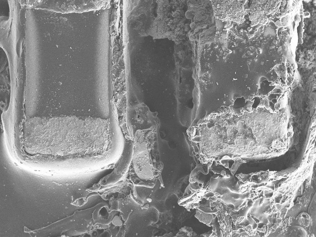
Testing according to IPC standards
Our analyses combine non-destructive and destructive testing methods and enable a comprehensive evaluation of materials, assemblies, and manufacturing processes in electronics manufacturing.
All tests are conducted in accordance with relevant standards, including:
- IPC-A-600 and IPC-A-610
- IPC-6012
- IPC-J-STD-001 as well as
- Test methods specified in IPC-TM-650
For the testing of electrostatically sensitive components, certified ESD-protected zones and trained personnel are available.
An overview of our analyses
Solder Joint Inspection
Identifying and analyzing solder joint problems
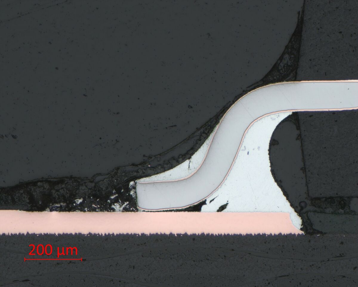
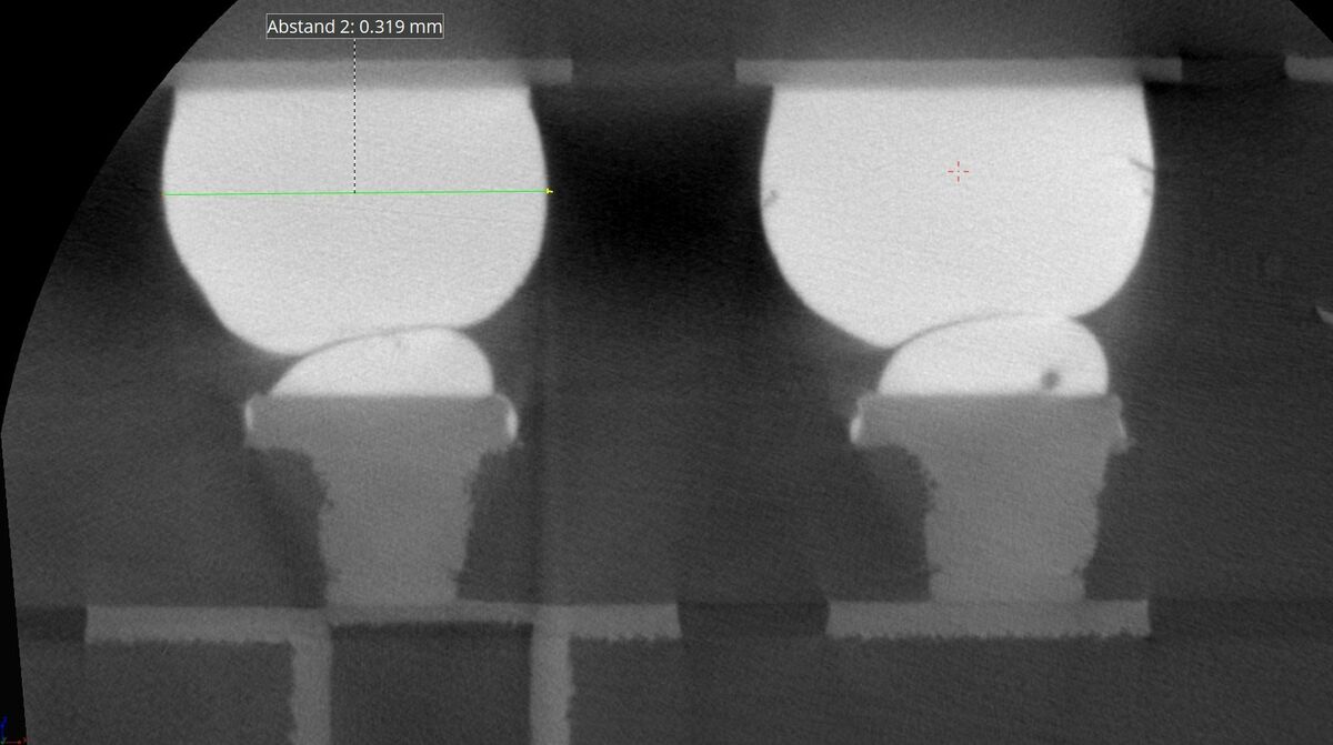
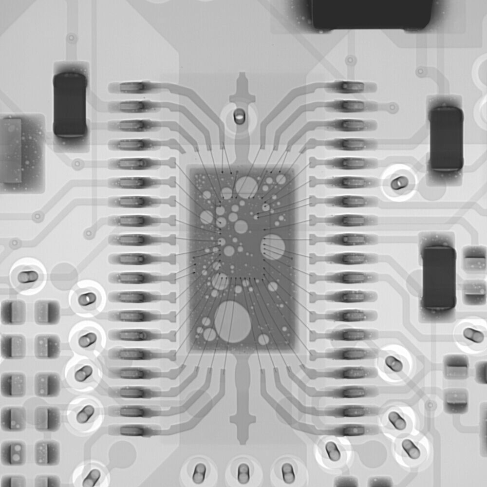
Defective solder joints are among the most common causes of failures in electronic assemblies. Especially in complex designs such as BGA components or integrated circuits, microcracks or voids can lead to intermittent electrical faults. We support you in solder joint analysis to identify problems in solder joints and understand their causes.
Our analyses answer the following questions, among others:
- Why do solder joints fail under thermal or mechanical stress?
- Are solder joints made in accordance with standards?
- Are there voids, cracks, or wetting issues?
Solder joint analysis methods:
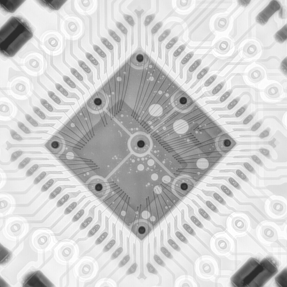
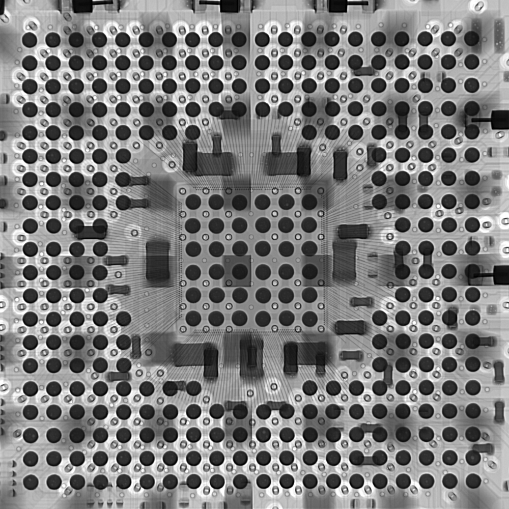
For our investigations, we combine non-destructive methods such as 2D X-ray analysis (AXI) and 3D computed tomography with metallographic section analysis and microscopic examinations.
For BGA components, the Dye-and-Pry test (IPC-TM-650) enables a targeted examination of microcracks and delaminations in solder joints.
PCB Inspection
Detecting defects on Printed Circuit Boards (PCB) early
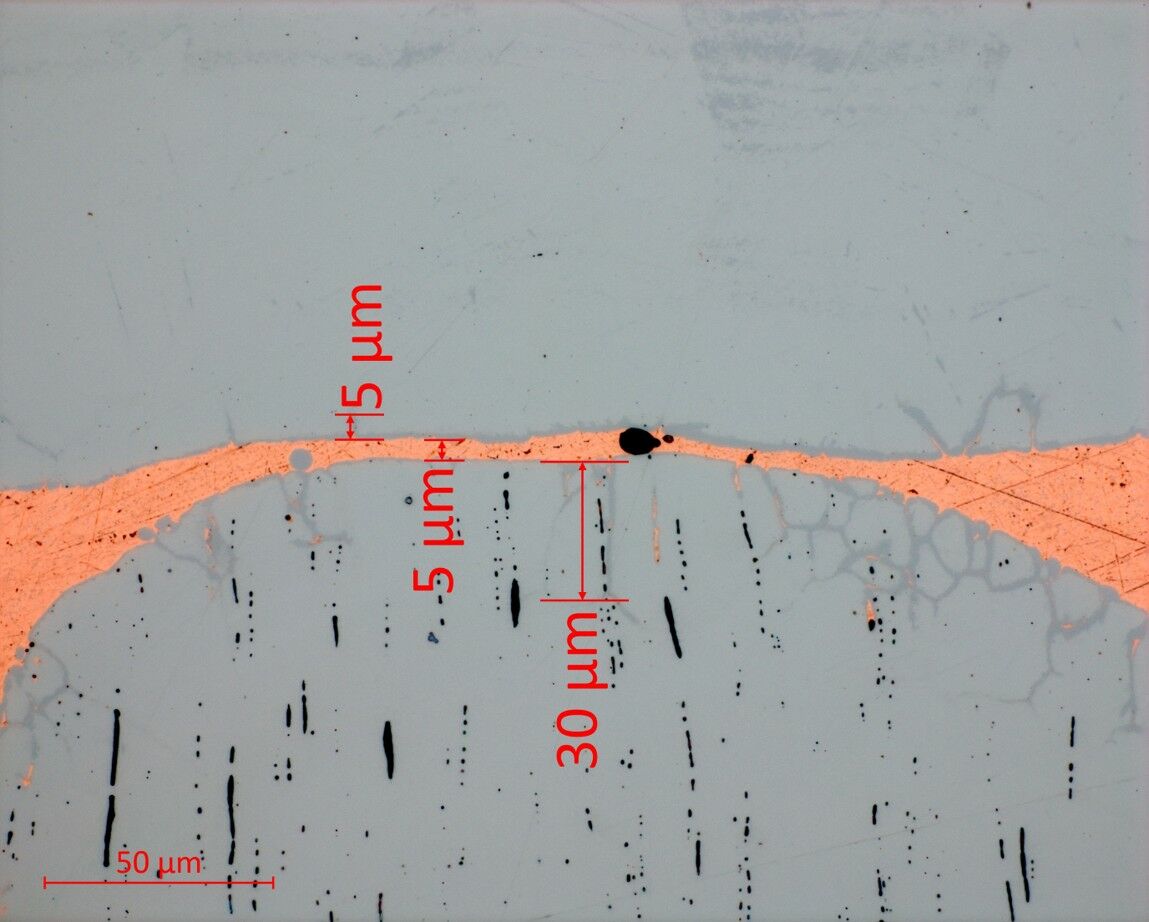
Defects in printed circuit boards can lead to short circuits, contact issues, or reliability problems. The causes often originate in the manufacturing process—for example, in the metallization of through-holes, the layer structure, geometric deviations, or material defects.
Typical questions from our customers:
- Are through-holes correctly metallized?
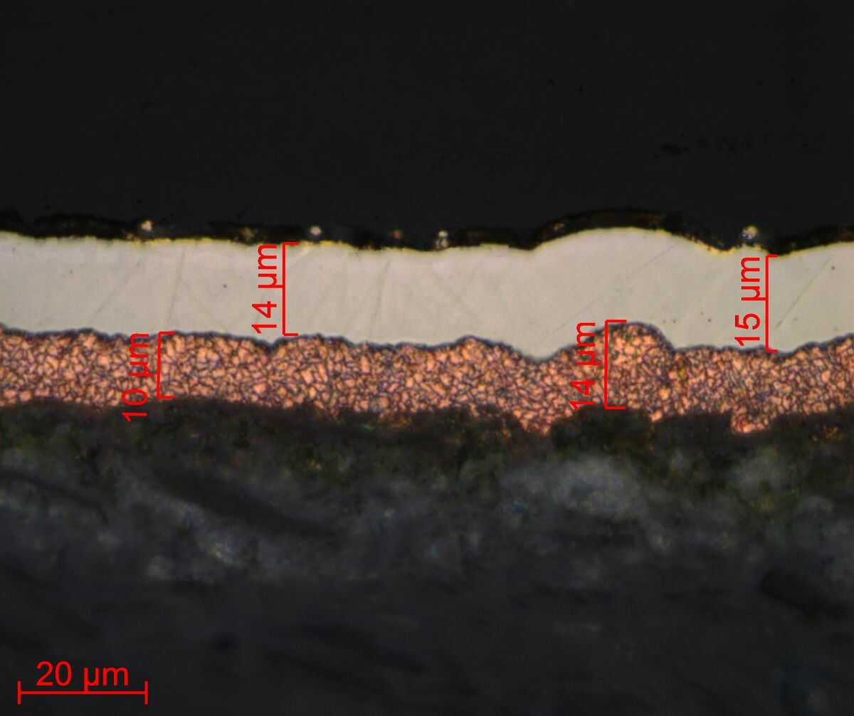
- Do copper thicknesses and layer structure meet specifications?
- Are there structural defects or delaminations?
- Do trace widths, spacing, and via diameters match the design specifications?
Test Methods for Printed Circuit Board Analysis:
A systematic examination of assembled and unassembled printed circuit boards (PCB / PCBA) allows problems to be identified at an early stage. We conduct our examinations in accordance with IPC-6012 and the acceptance criteria of IPC-A-600.
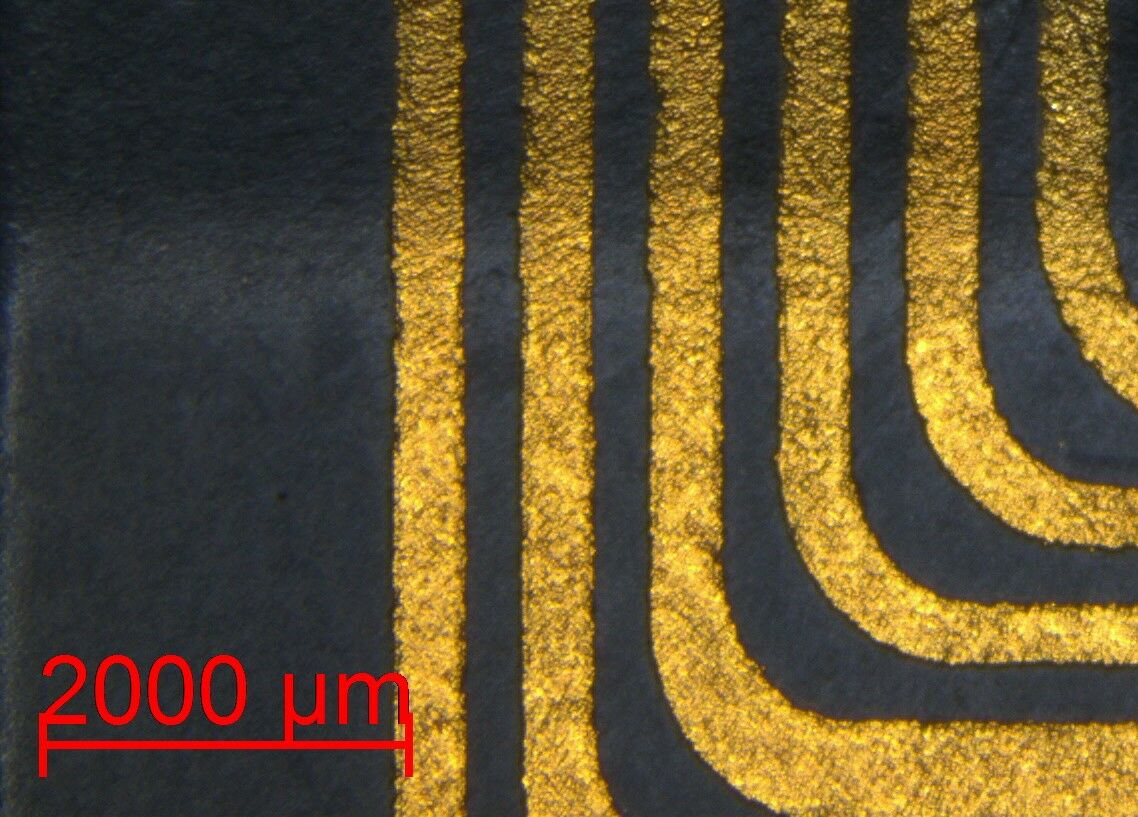
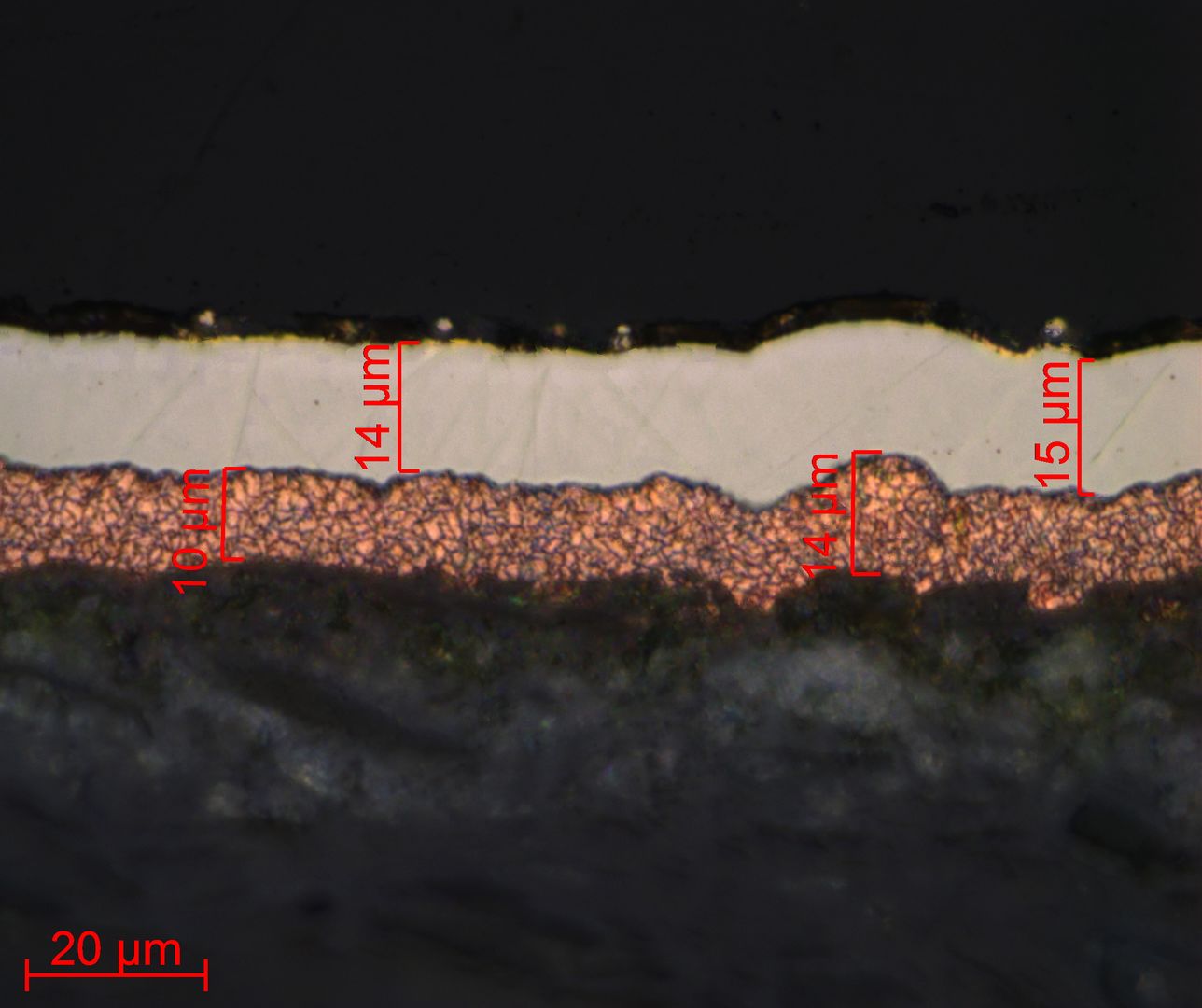
We use methods such as PCB microsection analysis / microsections, microscopic examinations, layer thickness measurements as well as dimensional measurement techniques. This is supplemented by material analyses to reliably identify manufacturing defects (even before the assemblies are populated).
Geometric Inspection
Identifying geometric deviations in Printed Circuit Boards
In addition to material or structural defects, geometric deviations can also lead to functional problems in electronic assemblies. Deviations in trace widths, drill hole positions, or PCB dimensions can impair the electrical function, solderability, or mechanical fit of components.
Typical Questions
- Do trace widths and spacing comply with design specifications?
- Are holes and vias correctly positioned and dimensioned?
- Do the PCB’s outline and dimensions match the specifications?
Our Analysis
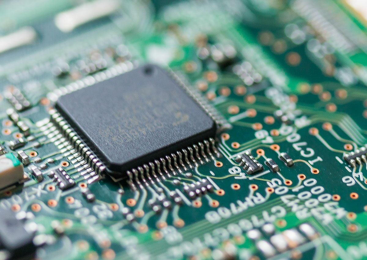
As part of the dimensional PCB inspection, we check critical geometries and dimensions of the PCB. These measurements complement the structural and material analysis and support quality assurance in accordance with IPC requirements.
-
© xiaoliangge - stock.adobe.com -
Contamination Analysis
Identifying Contamination on Printed Circuit Boards
Residues from manufacturing processes can significantly compromise the reliability of electronic assemblies. Ionic or organic contaminants can cause leakage currents, corrosion, or wetting problems.
Typical challenges faced by our customers:
- Ionic residues from flux or cleaning chemicals
- Organic residues on component surfaces
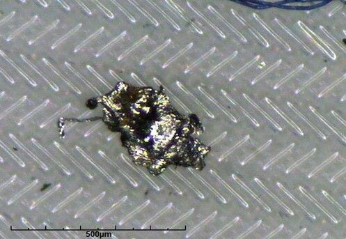
- Particles or fibers on printed circuit boards
- Unexplained electrical malfunctions
Test methods for contamination analysis:
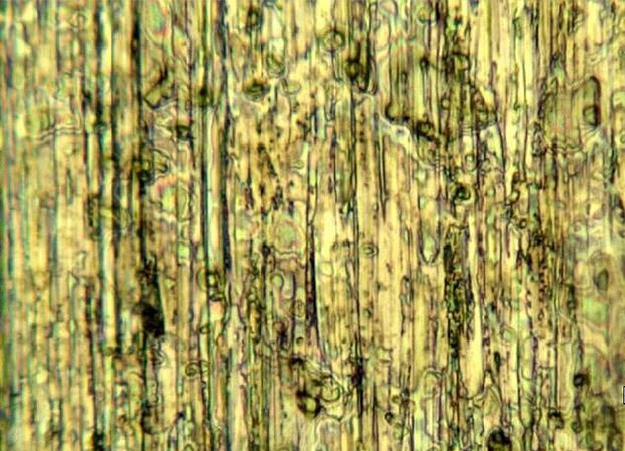
Cleanliness testing of printed circuit boards and electronic assemblies helps identify critical process residues.
- Ionic contamination using ROSE testing (IPC-TM 650 2.3.25) and ion chromatography (IPC-TM 650 2.3.28)
- Chemical-filmic (organic) residues using spectroscopic and chromatographic methods
- Particles and fibers by microscopic and spectroscopic particle analyses
Defect Analysis
Understanding the causes of component defects
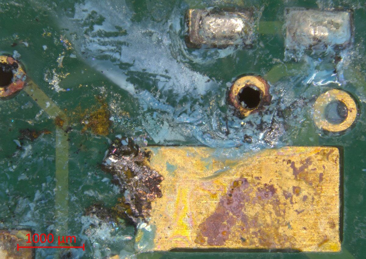
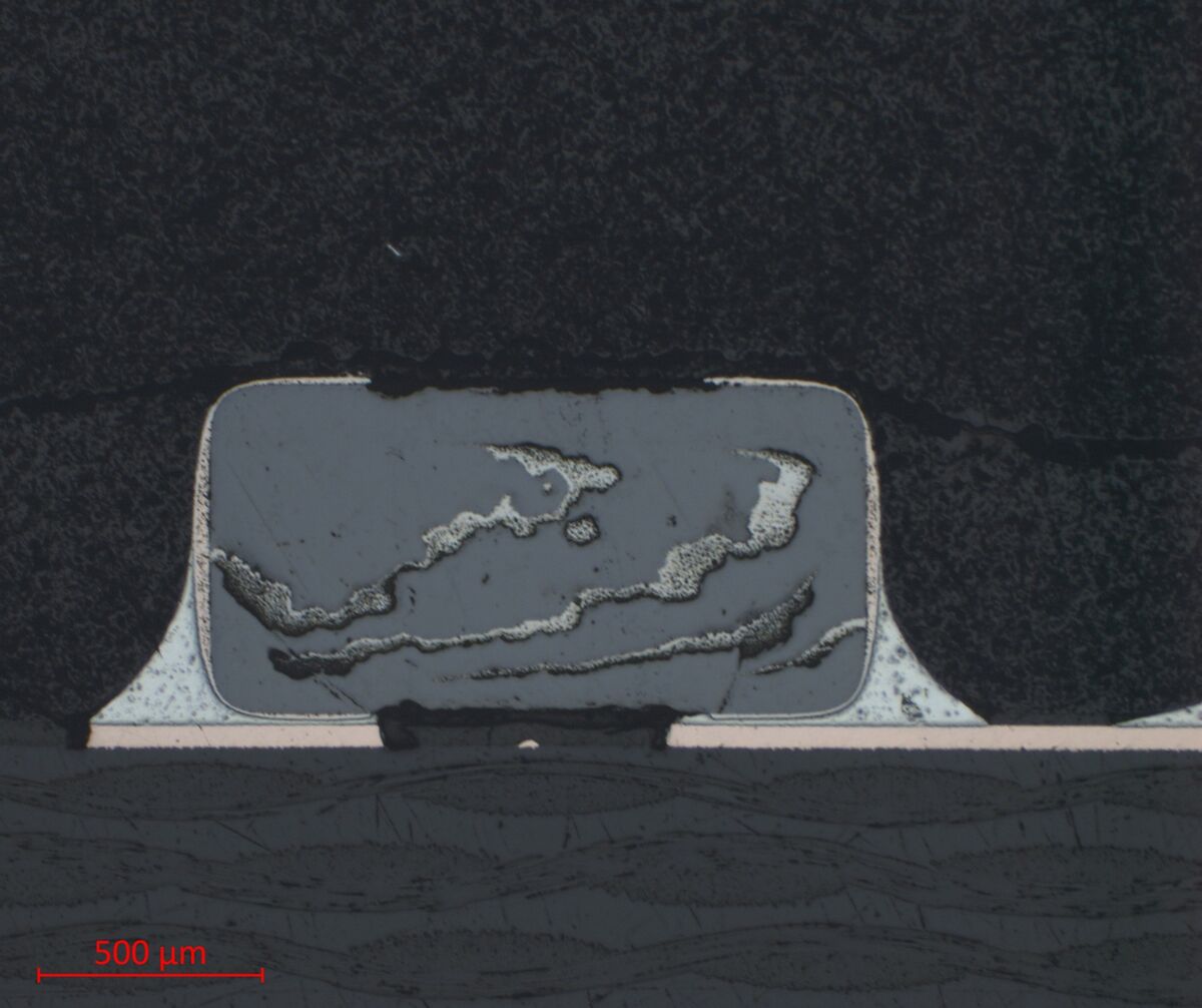
When electronic components fail during testing or in the field, a systematic failure analysis is required to identify the actual cause of the failure. As part of an Electronics Defect Analysis, we analyze components holistically—from surface analysis to the examination of complex material structures.
Typical analyses include:
- Investigation of material and manufacturing defects
- Analysis of delaminations, cracks, or inclusions
- Chemical analysis of deposits and residues
Our Approach
In defect analysis of electronic assemblies, we combine various analytical methods from materialography and chemical analysis to clearly identify manufacturing, material, or process issues.
Coating Analysis
Analyzing material and coating issues
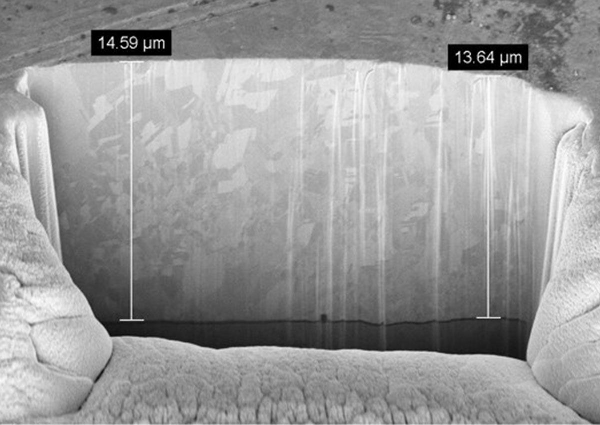
The quality of metallization, coatings, and conductive traces has a significant impact on the electrical and mechanical reliability of electronic assemblies.
Our analyses include:
- Analysis of the coating structure of conductive traces and coatings
- Investigation of conductive trace defects
- Inspection for signs of oxidation or corrosion
- Material identification of coatings
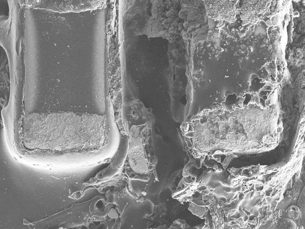
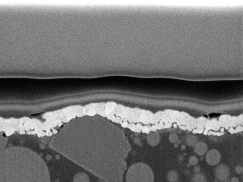
We use metallographic section analyses as well as high-resolution microscopic techniques (e.g., FIB-SEM) and spectroscopic methods. The analysis of coatings and metallizations helps to detect material problems or process deviations at an early stage.
In-Depth Analysis
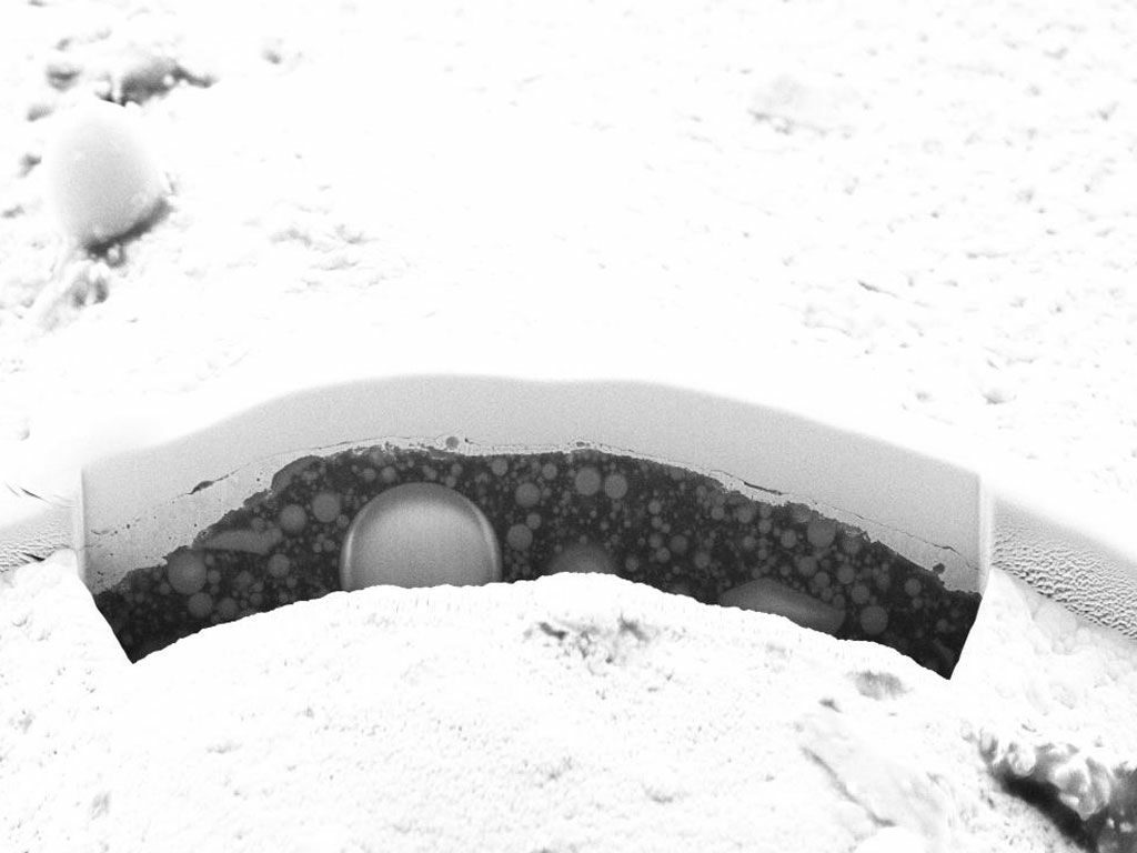
Semiconductor Analysis and Depth Analysis with FIB-SEM
Complex electronic components and chips require analysis at the nanoscale.
FIB-SEM analyses enable:
- Creation of cross-sections directly within the material
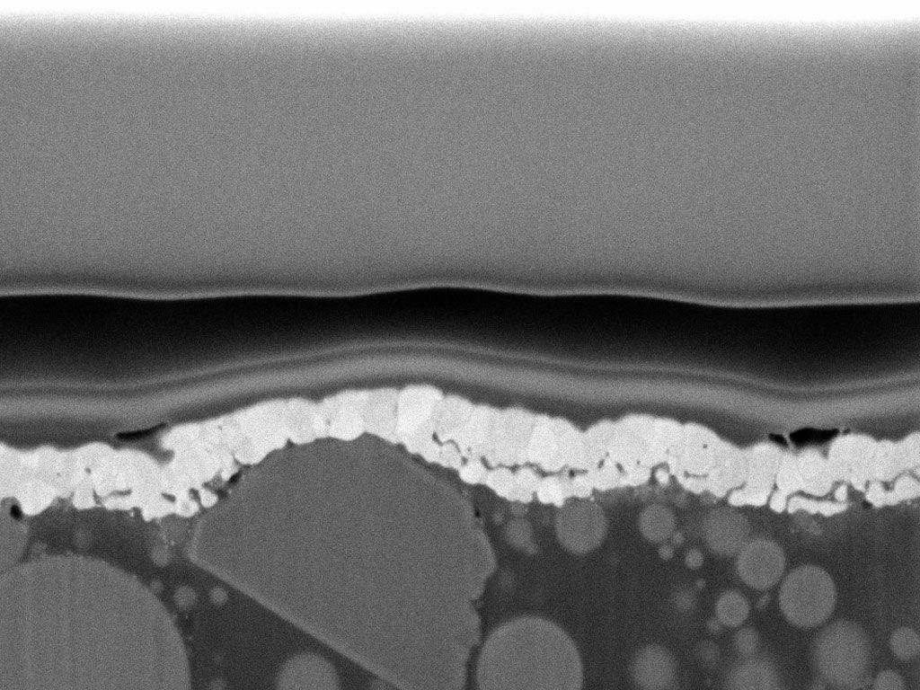
- Examination of sensitive layer systems
- Analysis of semiconductor structures and material interfaces
These examinations are an important part of semiconductor failure analysis of modern electronic components.
Contact us –
expert support is just a conversation away.
Using state-of-the-art analytical methods, we assist you with quality issues, damage claims, and development challenges – providing precise, well-founded, and solution-oriented support.

Frequently asked questions about Electronics Manufacturing
Here you'll find answers to the most important questions about the analysis of electronic assemblies.
Electronic assemblies can fail for various reasons. Common causes include microcracks in solder joints, delamination between material layers, voids in solder joints, material defects in printed circuit boards, or process contamination from flux residues or particles.
A systematic failure analysis of electronic assemblies helps to clearly identify these causes and determine appropriate measures for process improvement.
Solder joints can fail due to thermal cycling, mechanical stress, or process errors. Typical failure modes include microcracks, voids, or wetting problems.
To investigate such defects, methods such as 2D X-ray analysis, metallographic section analysis, or dye-and-pry tests are used, which enable a detailed solder joint analysis and BGA failure analysis.
The Dye-and-Pry Test is a destructive testing method used to analyze solder joints under ball grid arrays (BGA). In this process, a dye is injected into potential cracks or delaminations. After the component is pried off, these defects can be visualized under a microscope.
The method is frequently used in BGA failure analysis and solder joint analysis.
A failure analysis of electronic assemblies is useful when: Assemblies fail during testing or in the field The causes of customer complaints need to be analyzed New manufacturing processes need to be validated Material or process issues are suspected The goal is to identify the exact cause of a defect, such as material defects, process deviations, or solder joint issues. Non-destructive and destructive analysis methods are combined for a systematic investigation to perform a root cause analysis.
Contamination on printed circuit boards can result from flux residues, process chemicals, or particles and can compromise the electrical reliability of assemblies. Methods such as ROSE testing, ion chromatography, and spectroscopic and microscopic analyses are used for detection. These tests are part of PCB cleanliness testing and contamination analysis in electronics manufacturing.
The cleanliness of printed circuit boards is verified through so-called PCB cleanliness tests. These include methods such as the ROSE test for determining the total ionic residue (IPC-TM 650 2.3.25) and ion chromatography (IPC-TM 650 2.3.28) for the detailed analysis of individual ions. In addition, spectroscopic methods can be used to identify organic contaminants.
Ion chromatography (IC) is used to qualitatively and quantitatively determine ionic residues on printed circuit boards. These include, for example, Anions (bromide, chloride, fluoride, nitrate, nitrite, phosphate, sulfate) Cations (ammonium, calcium, lithium, magnesium, potassium, sodium) Organic acids (acetate, adipate, glutamate, malate, methanesulfonate, succinate, phthalate) Compared to the ROSE test, ion chromatography provides an analysis of individual ions. The analysis is performed in accordance with the IPC-TM 650 2.3.28 standard. The method enables a detailed assessment of ionic contamination in electronic assemblies.
FIB-SEM microscopy (Focused Ion Beam – Scanning Electron Microscopy) enables precise cross-sections to be created directly within the material with only minimal thermal and mechanical effects. This allows for the analysis of complex layer structures in modern semiconductors or chips and the investigation of defects as part of a semiconductor failure analysis.
As part of PCB inspection, dimensional measurements are also performed. This process verifies whether the PCB’s geometric properties comply with design specifications—for example, trace widths, trace spacing, drill hole and via diameters, residual ring widths, and the overall thickness of the PCB are checked. These measurements are an important part of PCB analysis and quality assurance in accordance with IPC standards to detect manufacturing deviations at an early stage.
What sets us apart:
Added value at Quality Analysis
Why we are your partner for the analysis of Printed Circuit Boards, Solder Joints, and Electronic Assemblies
IPC Standards
Standard-compliant evaluation of printed circuit boards, solder joints, and assemblies in accordance with relevant IPC acceptance criteria.

Process Optimization
Analysis results provide concrete approaches for improving soldering, cleaning, and manufacturing processes.
Root Cause Analysis
Rapid and structured failure analysis to identify material, manufacturing, or process issues.

Confidentiality
NDA/Confidentiality for data, test results, and components—project-specific and binding.

Clear Basis for Decisions
Customized reports and analyses provide a solid foundation for production approvals, system integration, or claims processing.

Linked analytics
Non-destructive testing, metallography, microscopy, and chemical analysis in a coordinated analytical approach.
Using advanced testing technology and specialized analytical methods, we support electronics manufacturing companies in the analysis of printed circuit boards, solder joints, and electronic assemblies.
Accredited test laboratory
for Electronics Manufacturing
Our DAkkS accreditation in accordance with DIN EN ISO/IEC 17025 stands for certified quality and maximum certainty. You benefit from test methods compliant with standards, validated methods and internationally recognized test results. As a reliable partner, we support you in the analysis of printed circuit boards, solder joints, and electronic assemblies.
Read more about the advantages our accreditation offers you:

Quality Analysis
The right partner for
Electronic Assemblies
What can we analyze for you?
We would be pleased to advise you about the numerous possibilities and combined analytical methods. Our goal: the best, most cost-effective and most efficient analysis of your material or component.